Histogramming Firmware - Rev 1 HTR Boards (2002)
There are 2 different versions of this firmware. The link provided
is a zip file that contains the firmware for the Xilinx and Altera FPGAs
on the HTR, with additional Xilinx implementations for boards SN10 and
SN12, as these boards have had to have several signals rerouted.
-
4-channel histogrammin
- full histogramming on the top 4 fiber inputs (includes
mcs file)
-
v1: LEMO L1A only (zip not available, but mcs
is)
-
v2: LEMO L1A or RJ45 L1A (zip
and mcs
only)
-
8-channel histogramming - full histogramming on all 8 fiber inputs (includes
mcs file)
-
v1: LEMO L1A only (zip not available, but mcs
is)
-
v2: LEMO L1A or RJ45 L1A (zip
and mcs
only)
Each fiber input to the HTR contains information from 3 different QIEs,
and each QIE has 4 different capacitors. This makes a total of 12
different inputs which need to be histogrammed on a given fiber.
There are 8 fibers, giving a total of 96 histograms needed. The Xilinx
XCV1000E has only 96 different block RAMs, and 32 are used (in the 8-channel
implemetation) just for the asynchronous FIFOs and the VME spy FIFOs.
Memory for the histogramming is implemented in distributed RAM due to insufficient
block RAMs. Actually, there are enough block RAMs for the 4-channel
implementation, however we simply used the same verilog files for both
4- and 8-channel projects.
Implementation
Each distinct QIE/CAPID on any given fiber appears once every 4 clock cycles
due to the rotation cap id's. This gives us 4 clock ticks in which
to perform the histogram filling. For each QIE/CAPID pair, 32 16-bit
words of distributed RAM are allocated. When the particular capid
appears, the mantissa is used as a lookup into distributed RAM for the
frequency of that particular value appearing. The number retrieved
is incremented and restored in the same memory location. This is
implemented with a state machine that does its job in 4 clock ticks, ready
for the next appearance of the particular QIE/CAPID. Each QIE/CAPID
distributed RAM (the histogram) is distinct from all others in the firmware
implementation.
Powerup: At powerup, or on a hard reset (VME write
of 0x1 to LocalBus CSR, address 0x10 on the LocalBus), histogramming is
disabled, and transmission to the DCC is disabled.
LEDs: The top bank of 2 LEDs is the same heartbeat
signal as always from the Altera. The lower bank of 4 LEDs, from
the Xilinx, has the same meaning as in the regular firmware:
-
LED1 is a heartbeat, indicating a good clock
-
LED2 indicates whether real-time histogramming and transmission to the
DCC is enabled or disabled
-
LED3/4 mux the receiver DV (data valid) and ER (error) bits depending on
the position of the dial (0 for fiber 1, 1 for fiber 2,...7 for fiber 8).
Xilinx firmware version: The 4-channel firmware has
version 0x25 (0x23 before the LEMO_L1A feature
was added), the 8-channel firmware has version 0x26 (0x24 before the LEMO_L1A
feature was added). Firmware versions are determined via a VME read
from the LocalBus address 0x24 (FPGAversionN in the documentation).
VME configuration needed to implement
histogram: There are only 2 things you have to do in
order to get histograms to be filled and written to the DCC:
-
Set the HTR card number (VME write to LocalBus address
0x20, HTRsubmodN in the documentation). The lower byte of thiis word
will be written into the header of the data sent to the DCC (see below).
-
Global Enable. The value of the histogramming global enable is reflected
in LED2, and is default not asserted. Global enable is asserted (released)
by issuing a VME Start (Stop) to the HTR card. This is the same VME
Start/Stop as in the regular firmware: writing a 0x4 to LocalBus
CSR (address 0x10) gives a VME Start, and writing a 0x8 gives a VME Stop.
Note that the VME Start/Stop signals are pulses in the HTR, however Start
is a set, Stop is a reset, on a FF which serves as the global enable.
Mantissa and Exponent: If the exponent is identically
0, the value of the mantissa is used for the histogram. If the exponent
is nonzero, the last bin in the histogram (bin 31) will be increment regardless
of the mantissa value.
4- vs. 8-Channel Firmware: Since there is only enough
RAM to hold 48 histograms (4 fibers x 3 QIE x 4 CAPID), the firmware will
alternate between FILL+SEND histograms from fiber inputs 1-4 and fibers
5-8. This translates into a "live time" of 50% (transmission to the
DCC is neglected since it is only a few % of the filling time).
Readout
Readout is either via VME, or the DCC:
Readout via DCC: At powerup, or on a hard reset
(VME write of 0x1 to LocalBus CSR, address 0x10 on the LocalBus), histogramming
is disabled. To start histogramming, issue the proper VME commands
as described above - VME_Start and VME_Stop controls
the entire histogramming and transmission to the DCC. Once you start
it, the DCC will begin to see data after approximatley 7 ms. The
histograms will be filled as soon as the VME Start signal is asserted inside
the Xilinx chip. The sequence of events are as follows:
-
Since each bin is described by a 16-bit word, we have to limit the histograms
such that there are no more than 65535 (216 -1) entries in any
one histogram. Since there are histograms for each capid, and
each capid appears once every 4th clock cycle (using the ~35MHz clock),
then histogram filling will be disabled 262,143 (218-1) clock
cycles after beginning, or approximately 7.5ms (262143/f where f is the
actual clock frequency run at the testbeam). Actually, to be
safe, we stop the histogramming after a maximum number of fills which is
less than 65535 fills, since there are a few setup clock ticks and we don't
want to be on the edge. This will mean that if you used the simulator
and sent the same value every time, the resulting histogram will have something
like 65532 or 65533 or 65534, etc., in the single bin. This
was checked phenomenologically. Or, in other words, each histogram
that you will have in the end will have a total of almost, but not quite,
65535 counts integrated over all bins.
-
As soon as the filling is complete, an internal enable
is released, and a signal is sent to the module that controls sending data
to the DCC. This module reads the histograms from all fibers one
bin at a time, filling FIFOs. Each memory read (each bin) is followed
by a write to the FIFO input, and a write of 0x0 to the bin to clear the
memory so we are ready for the next cycle. Each FIFO contains the
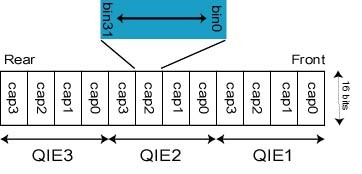
entire set of histograms from a given fiber: 3 QIE x 4 CAPID = 12
histograms, x 32 words (16-bit) = 384 deep, packed as shown in the figure.
-
As soon as the fifo's are filled, the module then reads the FIFOs and sends
data to the DCC. The reason for the intermediate FIFO stage is to
allow data to be sent to the DCC on each clock edge.
Synchronization with source position:
In order to try to synchronize the source posistion with the histogram,
the following has funcctionality has been added:
-
The HTR has a LEMO input for L1A as well as an RJ45 L1A input. Every
time the source position is read out, a pulse (between 100ns and a microsec
or so) should be sent to the HTR in ether the LEMO L1A or the RJ45
input. Internally, the two L1As are or'd together so you can use
either one. This pulse will be used to latch the event number
of the current histogram (EVN_LATCHED). Note that this event number
(EVN) is incremented every time histogram FIFOs are reset, which always
happens after the block of histograms is sent to the DCC. That is,
EVN will be 0 on the first histograms sent to the DCC (fibers 1-4 for the
8-channel firmware) and 1 for the next histogram (fibers 5-8) and so on.
-
The event number EVN will change only every ~7.8ms. The latched EVN
will be stored in the data stream as described below.
DCC Data Format: The data sent to the DCC will
have exactly the same format as the data sent using the regular firmware,
namely a 6-word header followed by data followed by a 2-word trailer, with
each word having 16-bits. The format of each is:
-
Header
-
Word 1: {8'h0,evn[7:0]}
-
bottom 8 bits are the bottom 8 bits [7:0] of a 2-bit event number (EVN)
(note this is 20 bits, not 24 bits)
-
top 8 bits are all zero
-
Status bits: 2'b11
-
Word 2: {4'h0,evn[19:8]}
-
top 4 bits identically 0, followed by the top 12 bits [19:8] of the event
number (EVN)
-
Status bits: 2'b10
-
Word 3: {16'd1544}
-
word count = 6Header + Data + 2Trailer. Histograms of 4 fibers results
in 4 x 12 x 32 = 1536 words, so the word count will be 1544. Test
versions of the firmware that have fewer than 4 fibers histogrammed will
have a smaller number here.
-
Status bits: 2'b10
-
Word 4: {1,mux,6'h3,8'h2}
-
Bottom 8 bits are set to 0x2 (0000 0010).
-
Next 6 bits are set to 0x3 (0000 11). This indicates that there will
be 4 histograms in the data block.
-
Next bit is called the "mux" bit, and is used to indicate which set of
fibers are used to fill the histograms: when this bit is 0, histograms
are from fibers 1-4, and when this bit is 1, histograms are from fibers
5-8. Note that this bit should be the same as the lower bit of the
event number EVN as a check. EVNs that are even are during histogramming
and transmission to the DCC for fibers 1-4, and EVNs that are odd are for
fibers 5-8.
-
The next bit, MSB, is set to 1 for arbitrary reasons.
-
Status bits: 2'b10
-
Word 5: {EVN_LATCHED[19:12],hcn[7:0]}
-
Bottom 8 bits are the heater card number as described above.
-
Top 8 bits, usually reserved for the orbit number, are used for the upper
8 bits of the latched EVN, triggered off LEMO_L1A
as described above.
-
Status bits: 2'b10
-
Word 6: {trigger_type[3:0], EVN_LATCHED[11:0]}
-
The bottom 12 bits are reserved for the bunch crossing number. In
this case these bits are used for the upper 12 bits of the latched EVN,
triggered off LEMO_L1A as described above.
-
The top 4 bits are the trigger type. For histogramming, this is set
to 5.
-
Status bits: 2'b10
-
Data.
-
Each successive data word as is read from the FIFO, therefore the data
is packed exactly as the FIFO is packed. See above.
-
Status bits: 2'b10
-
Trailer
-
Word 1: {16'h0}
-
All bits set to 0 in the HTR, set to the number of 32 bit words (word 3
of the header/2) by the DCC.
-
Status bits: 2'b10
-
Word 2: {evn[7:0],8'h0}
-
Bottom 8 bits are set to 0 in the HTR, and used for error flagging by the
DCC.
-
Top 8 bits are set to the same as the bottom 8 bits of word 1 in the header,
namely the bottom 8 bits of the event number.
-
Status bits: 2'b01
Software example
Since we did not have a working S-Link transmitter card (LSC) at Maryland,
we tested the HTR->DCC link by reading data out of the DCC through VME.
We used Eric Hazen's htr_test program to reset the HTR, set the module
number, and issue the VME_Start. Then we used Eric's "shell" with
the DCC_capture.vme script to read out the DCC and dump the data into a
file. The file, a byte stream, is then read in and decoded, with
histograms dumped to disk formatted. The program we used to decode
the data is included below. It will keep reading blocks ("events")
as long as you don't bail.
#include <stdio.h>
#include <stdlib.h>
#include <math.h>
/* this file takes the output from the shell that eric wrote, which
dumps a histogram file to disk, and then (this program that is)
prints the histogram for you so it's easy to see what was sent
*/
int main(int argc, char* argv[]) {
////////////////////////////////////
///make initial declarations here...
////////////////////////////////////
int i,j,k,m,n,p, word;
if (argc<2) {
printf("you must specify an input file to use
this");
return 0;
}
FILE* f=fopen(argv[1],"r");
if (f==NULL) {
printf("Cannot open '%s'.\n",argv[1]);
return 1;
}
//
// read file. format is 6 words of header, data, 2
words of trailer
//
unsigned short buff[1544]; // 1544 is enough
int ret;
int ibr = 0;
while (ibr == 0) {
ret = fread(buff, 2, 1544, f);
//
char tch[80];
int header1 = buff[0];
int header2 = buff[1];
int header3 = buff[2];
int header4 = buff[3];
int header5 = buff[4];
int header6 = buff[5];
/* printf("Header word Value\n");
printf(" 1
0x%4.4X\n",header1);
printf(" 2
0x%4.4X\n",header2);
printf(" 3
0x%4.4X\n",header3);
printf(" 4
0x%4.4X\n",header4);
printf(" 5
0x%4.4X\n",header5);
printf(" 6
0x%4.4X\n",header6);
printf("Trailer word Value\n");
*/
int wcnt = header3;
int trailer1 = buff[wcnt-2];
int trailer2 = buff[wcnt-1];
/* printf(" 1
0x%4.4X\n",trailer1);
printf(" 2
0x%4.4X\n",trailer2);
*/
//
// event number:
//
int ev1 = header1;
int ev2 = header2;
int evn = ev1 + 256*ev2;
printf("Event number %d ",evn,ev1,ev2);
//
// heater card number
//
int hcn = header5 & 0xFF;
printf("HTR card number %d\n",hcn);
//
// word count:
//
printf("Word count %d ",wcnt);
//
// number of histograms: (word count - 8 for
H+T, divided by 32 bins/hist
//
int nhists = (wcnt - 8)/32;
//
// number of fibers: 12 histos per fiber always
//
int nfibers = nhists/12;
printf("Number of fibers = %d and number of
histos = %d\n",nfibers, nhists);
//
// trigger type
//
int ttype = header6;
ttype = header6 >> 12; // shift
down 12 bits
printf("Trigger type %X - should be 5 for histogramming\n",ttype);
//
// mode, nfiber check, and mux bit
//
int mode = header4 & 0xFF;
if (mode == 2) printf(" Histogram
mode confirmed\n");
else printf(" Mode not
right! We decode 0x%X\n",mode);
int nfibs = header4 >> 8; // shift right
8 bits
nfibs = nfibs & 0x3F;
printf("Fibers from header word 4 = %d\n",nfibs+1);
int muxbit = header4 >> 14; // shift down
14 bits
muxbit = muxbit & 1;
printf("Muxbit this histogram set to %d\n",muxbit);
//
// latched event number
//
int lev1 = header5 >> 8; // shift
down 8 bits
int lev2 = header6 & 0xFFF; // mask off
upper 4 bits
int evnl = lev2 + (lev1 << 12);
// shift lev1 up 12
printf("Latched event number = %d\n",evnl);
//
// trailer:
//
printf("Trailer word 1 = %d (should be %d)\n",trailer1,wcnt/2);
int trailer_evn = trailer2 >> 8;
// shift down 8 bits
printf("Trailer evn[7:0] = %d (should be %d)\n",trailer_evn,ev1);
n = 6;
//
// histograms are packed: 32 bins at a
time
// packing is: fiber1:qie1:capid0:bins0-31
and then capid1:bins0-31 ad nasuem
//
ibr = 0;
for (i=0; i<nfibers; i++) {
printf("\n
Histograms from fiber %d\n",i);
if (ibr == 1) break;
for (j=0; j<3; j++) {
if (ibr == 1) break;
printf("
QIE number %d\n",j);
unsigned short qiebins[4][32];
p = 0;
for (k=0; k<4; k++)
{
for (m=0;
m<32; m++) {
qiebins[k][m] = buff[n++];
}
}
//
// printout in columns
for convenience
//
printf(" Bin
CAPID0 CAPID1 CAPID2 CAPID3\n");
for (m=0; m<32; m++)
{
printf("%3d
%6d %6d %6d %6d\n",m,
qiebins[0][m],qiebins[1][m],qiebins[2][m],qiebins[3][m]);
}
printf(" HIT <n>
for next QIE or anything else to exit: ");
int ret = scanf("%s",tch);
if ( ret == 0) ibr =
1;
if (tch[0] == 'n' ||
tch[0] == 'N') ibr = 0;
else ibr = 1;
}
}
}
fclose(f);
}
Last modified 7/28/02 Drew
Baden